How To Test Motherboard With Multimeter
Many people are sure that their motherboard is not working properly but don’t know what to do. To now the status you need to perform some tests. Multimeter is good for testing but how motherboard mot rd with multa imeter? With some tests and using some instwillns, you will see the results in the form of readings.
In this guide I, will help you to check for the voltage, resistance & short circuit using the multimeter. Following these ways you can easily predict the motherboard problems. Through this, y,ou will know when to change the motherboard.
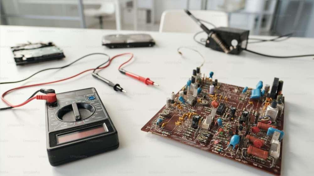
Introduction To Multimeter
Actua lly, it’s an electrical testing tool. So what’s the function of a multimeter? Actua lly, it is useful to measure the resistance, volt voltagend continuity. In order To the electrical components such as the motherboard it can be useful.
Probs
It has overall 2 probes.
Red Probe: it’s useful to test for the positive voltage.
Black Probe: useful for testing 0 volts or ground testing
Instructions To Use
If you are using a multimeter you must set it in the right position. That’s why if you are looking for testing the voltage you first need to set the settings to DC voltage. However, you, nee,d to set it to the continuity in case of testing the continuity.
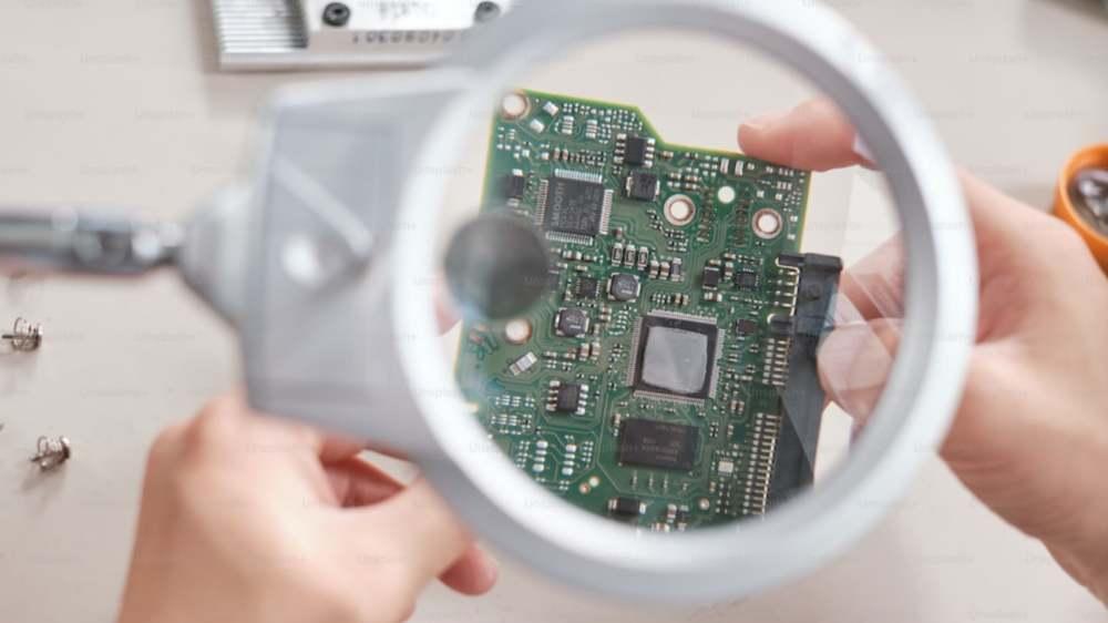
How To Know If A Motherboard Is Bad?
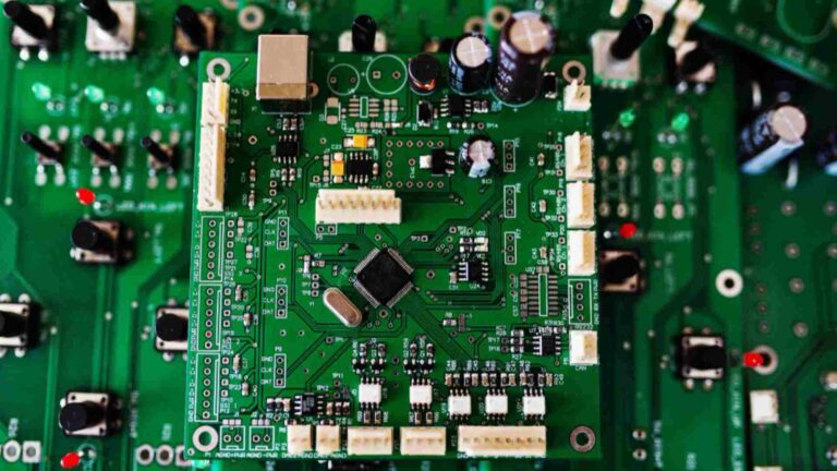
A motherboard is a printed circuit board as a result it will connect all of the computer’s components. However, if it is faulty then it might stop working. There Multiple signs areul to diagnose if your motherboard is not actually present in a good condition. Some of its common identifications are including;
- Your computer will start to freeze frequently.
- It fails to recognize some of the hardware components such as RAM.
- Overheating of the PC
- Moreover, your computer fails to start.
- Additionally you will observe a burning smell on the motherboard.
- Beeps from the computer.
How To Test Motherboard With Multimeter For Testing Voltage?
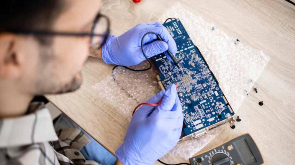
If you are facing the issues in starting your computer the problem might be due to the voltage issues. If you see the computer suddenly crashing then go for the voltage test. It can be easier to self test the voltage at home.
To test it you need a multimeter. If there’s any problem within the hardware or your computer it might be due to the voltage fluctuations. You can easily purchase it from different websites & stores. Afterwards, follow these steps;
- First of all, disconnect all of the connected sources to your computer.
- You must remove all the cords with power supply or any type of battery too.
- Afterward on your motherboard find out the 20-pin ATX power connector. Usually, it appears near the top side of the motherboard.
- Now you need to set the multimeter to DC voltage through the settings.
- Afterwards there’s a positive terminal on the power connector that is showing red lead touch it.
- On the ground terminals touch the black lead.
- On the display now you will start to notice the reading that is shown in volts.
- If you don’t see any readings then you must need the check for the connection. However, make sure that you are touching the correct terminal leads.
- Repeat these steps & take more readings in the same way.
- Now observe if all readings appear in the normal range or not.
- If you observe reading within the range then the motherboard is not causing any disturbance within the computer.
- However, if you are observing reading out of normal range then there’s a problem within the motherboard.
- Moreover, you can have it checked by the technician to diagnose further.
Evaluation Of Results
First of all, for the pin 8 the power supply must be above then the 2.5 V. It’s actually the required voltage for the computer to start. Upon resetting the value must drop to zero and then spears the exact 2.5V.
- In case of pin 9(VSB) the voltage must be above then the 5 volts.
- However when it comes to the pin (PS-ON) the value drops to zero.
- Beyond this if you observe any other reading then indicates a fault. For that purpose the motherboard actually fails to give the performance.
How To Test Motherboard With Multimeter For Testing Resistance?
Equipments
Multimeter, multimeter probes and a screwdriver
1. Disconnect The Power From Motherboard
Here’s no need of passing current for the measurement of resistance. Unplug the device and wait for sometime so the current will drain out completely. You have to wait for at least 5 to 10 minutes.
2. 200 Ohm’s Range Is Enough To Set On The Multimeter
Resistance is actually measured using the ohm units. It can be represented using the symbol (Ω). The lower range is 200 ohm’s and it’s an appropriate range to find out the exact results. However the readings will appear on the O.L form on the display to measure the ohms.
Make the two multimeter probes in such a way that they touch each other. Afterwards check that the reading must appear to be zero on the display. Alternative to this you can also place the 2 leads over the metal chaises to make the 0 Reading.
3. ATX Connector De-Attachment From Motherboard
The component known as ATX connector that supplies the power through the power supply unit to the motherboard. In order to use it for the motherboard the PSU converts the AC voltage to DC voltage (low power).
Disconnect the power connector to expose the PSU pins. However, pay attention to it so that you will not damage it.
4. Placement Of Probes & ATX Pins
First of all the resistance test will be performed on the connector. Afterwards you need to test for all the wires that are in a connection with the PSU. Also, you need to determine the resistance amount of these all.
- First of all, you need to place black lead over the computer’s metal chassis.
- Later on put the red lead on the GND (black color wires) on the connector.
- Actually, the black wires represent the ground connector.
- Moreover they are expected to give out the zero ohm reading on the device (multimeter).
- After the GND wires later on you can move towards the color wires.
- Likewise for the color wires place the black probe on the computer chassis. However, place the red ones over the colored wires.
- In the case of color wires, the resistance must be 50 ohms. However if it comes lower to this then you must need to change the connector.
5. Resistance Checking On PSU Pins
- After checking for all the wires later on, check for the PSU slots of the motherboard.
- However you must require the specific pin chart for the ATX-20.

- Later on test for the “COM” to check for the connector pins resistance.
- Now choose to place the negative probes over the computer’s metal chassis. Put the red probe on the black slots.
- You must check for the zero resistance reading at this point.
- However, if it appears within the low value then it’s the indication of PSU short. In that case, you need to replace the PSU or the whole motherboard.
- However the resistance for the color slots should be 50 ohms.
How To Test Motherboard With Multimeter For The Short Circuit?
However you can use different methods to check for the short circuit. Multimeter is the most useful way to measure the continuity between two points. Additionally ohmmeter can also be used to measure the exact resistance within the two points.
Reasons Behind Short Circuit In Motherboard
It’s important to know the cause behind fixing it. However if you don’t know about the exact reason then it’s better to check it from a professional person. In most of the cases the short circuit is due to;
- Loose connections
- Damaged components
- Incorrect wiring
How To Check a Short Circuit Using a Multimeter?
If still you are confused about how to test motherboard with multimeter? Perform the short circuit tests to explore the reasons.
- First of all you have to adjust the settings of the multimeter to the settings of continuity.
- Afterwards touch the 2 probe points that you think are shorted.
- Later on check for the reading on the multimeter.
- If it shows the low resistance or the beeps that means these 2 points have the short circuit.
FAQs
What Is The Voltage Of A Motherboard?
Most of the motherboards are usually with the 4-pin 12 Volts power connector that is near to the CPU. However some connectors also come with the 4+4-,pin connectors. Moreover the process area comes between the 1.1v to 1.3v only.
What Are Ways To Test A Motherboard?
For testing the motherboard the multimeter is a tool with high performance. For testing the right amount of power this tool is amazing.
Is Motherboard AC Or DC?
When it comes to the motherboard and all of its components including adapters and drives it works and requires the DC power foThe motherboard.
Conclusions
Motherboard is the main circuit board & connectivity backbone that connects all components of the computer. Sometimes it doesn’t work properly and you don’t know what to do.
Multimeter is a tool for knowing the exact problem. But how to test motherboard with multimeter? You need to follow some testing steps and it will give the results in the form of readings.
You can follow the above tests and check the status of your motherboard. However if you observe readings beyond the normal then the motherboard is problematic and you need to replace its components or motherboard depending on the problem.
For more information visit https://mindtechies.com/.